Accepted 17 March 2021
Available Online 26 March 2021
- DOI
- https://doi.org/10.2991/mathi.k.210322.001
- Keywords
- Crystal polyaniline
nanofibers
citric acid
conductive ink - Abstract
A series of Polyaniline (PANI) nanoparticles doped with citric acid were synthesized by situ polymerization. It is interesting that uniform nanofibers with the diameter of 50 nm formed under a proper mass ratio (aniline:citric acid) of 5:4, which forms 3D conductive networks. XRD patterns show the nanofibers have sharp peaks, corresponding to high crystallinity. The nanofibers were selected for preparation of PANI ink with Polyethylene Glycol (PEG, Mn = 698), Sodium Polystyrene Sulfonate (PSS, Mn = 70,000). The good electric conductivity of PANI conductive ink is 6.49 × 10⁻³ S/cm, where PANI inks of Anhui University of Science and Technology university was stamped in A4 paper for good printing performance acting as electronic circuit line turning on a LED light. Moreover, the effects such as the content of citric acid and PSS on the conductivity of PANI powder and also discussed.
- Copyright
- © 2021 The Authors. Published by Atlantis Press B.V.
- Open Access
- This is an open access article distributed under the CC BY-NC 4.0 license (http://creativecommons.org/licenses/by-nc/4.0/).
1. INTRODUCTION
Conductive polymer inks [1–5] are attractive for practical applications such as electronic circuit line, organic electrodes, sensors and capacitors, due to their printing performance, conductivity and chemical properties. Generally, nanofibers [6–9] are better conductive materials for inks because they can easily disperse and form 3D conductive networks [10,11]. However, the conductivity and stability of polymer inks are still not very high owing to disordered molecular chains of nanofibers [12–16]. Therefore, investigations in improving crystallinity of the nanofibers is a hot spot in preparation of high quality conductive polymer inks. Conductive ink generally refers to metal nanoparticles, metal nanowires, or transparent conductive oxide materials, such as indium tin oxide. These materials have high electrical conductivity, but they also have significant limitations. The main problem with total cost of ownership is the scarcity of available materials available to meet the continuous demand of global consumers, coupled with high production costs and poor mechanical flexibility may be a problem, however, recent progress reports indicate that total cost of ownership use is well tolerable to bending. Metal nanoparticles and nanowires are typically made up of metals such as gold, silver and copper, which are highly conductive but costly.
Here, we report a general route to create a series of Polyaniline (PANI) crystal nanofibers. The method takes place of room temperature and does not depend on any specific agents, equipment or heating, cooling and complex procedures, which is especially suitable for producing bulk quantities of high-quality and low-cost PANI crystal nanofibers for conductive polymer inks. The idea of preparing crystal nanofibers of PANI is very interesting and could potentially lead to significant advancements in polymer crystallization.
2. EXPERIMENTAL SECTION
All of the reagents including aniline, citric acid and Ammonium Persulfate (APS) are of analytical grade. They were used in experiments without further purification. Double distilled water was used throughout the experiment to prepare the solutions. Aniline, citric acid and APS were all purchased online. Aniline also known as anilin, anilin oil, amino benzene, molecular formula: C6H7N. Colorless oily liquid. Slightly soluble in water, soluble in ethanol, ether and other organic solvents. Aniline is one of the most important amines. Mainly used in the manufacture of dyes, drugs, resins, but also can be used as rubber vulcanization accelerator. It can also be used as a black dye itself. Citric acid is an important organic acid, the appearance is colorless crystal, odorless, has a strong sour taste, easily soluble in water. According to its water content, it is divided into monohydrate citric acid and anhydrous citric acid. APS, chemical formula: (NH4)2S2O8, contains peroxy group, is a strong oxidant. Mainly used as oxidant, bleach, disinfectant, photographic materials, analytical reagents, etc. Research shows that APS is widely used in battery industry as oxidant and bleaching agent. Using aniline, citric acid and APS as raw materials, PANI nanometer powder was prepared by in situ polymerization.
A typical experimental procedure in Figure 1 was as follows: The PANI-citric acid was synthesized by using 5 g of aniline, 5 g of APS and 1 g of citric acid in 400 mL water at room temperature. The prepared PANI-citric acid was washed three times with ethanol and deionized water. To understand the influence of doping on crystallization of PANI, a set of doping control experiments were performed with mass ratio (aniline:citric acid) of 7:1, 6:1, 5:1, 5:2, 5:3, 5:4, corresponding to sample “PANI 1–6” as shown in Figure 1, respectively, while the other synthetic parameters were kept constant. After drying of black PANI powders, pressed PANI plates are acquired at pressures about 10 MPa.
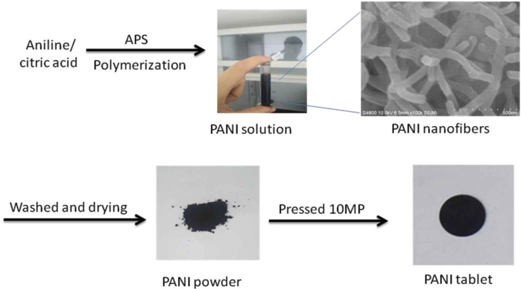
Procedure of the preparation of polyaniline powders: PANI 1–6.
A portion of the 5:3 (aniline:citric acid), with the highest conductivity PANI powder PANI-5 (3.289 × 10⁻² S/cm) was selected as raw material for inks. 1 g of PANI powder, 0.1 g of Polystyrene Sulfonate (PSS) and 0.1 g of Polyethylene Glycol (PEG) were mixed into a paste of black inks (Figure 7). A set of re-doping control experiments were performed with mass ratio (PANI:PSS) of 10:1, 10:2, 10:3, 10:4, 10:5, 10:6 in Figure 7, corresponding to sample “Ink 1–6”, respectively, while the other synthetic parameters were kept constant.
SEM studies by using a FEI-Sirion200 Scanning SEM, PANI powder solutions were drop-cast on the silicon substrates followed by drying for 12 h at 60℃. UV–Vis absorption spectra of the samples dispersed in distilled water, through ultrasonic irradiation, were obtained with U-4100 UV spectrophotometer in the range of 200–850 nm. XRD patterns were performed on a XD-6000 X-ray diffractometer using a Cu-Kα radiation source (λ = 1.5418 Å). The conductivity measurements of PANI powder tablet pressed under the pressure of 10 MPa were performed with the four-line probe approach by using a CINDBEST CS-6 four probe platform (Sendongbao Co., China) and a CHI660E electrochemical workstation (Shanghai Huachen Co., China), at room temperature. CINDBEST CS-6 four probe platform was used to check conductivity of the ink with microscopic inspection (Figure 1).
3. RESULTS AND DISCUSSION
3.1. Polyaniline Powders: PANI 1–6
3.1.1. Characterization of polyaniline
Figure 2a and 2b shows similar irregular nanoblocks of PANI 1 and 2. Figure 2c and 2d and present mess nanoblocks of PANI-3 and 4, respectively. With the increase ratio of aniline:citric acid of 5:3, uniformed nanofibers with diameter of 50 nm come out are observed (Figure 2e). Moreover, there nanofiber generate conductive networks. 2D layered nanosheets with the length of 2–3 nm can orderly self-assemble (Figure 2f). The thickness of the nanosheets is <50 nm.
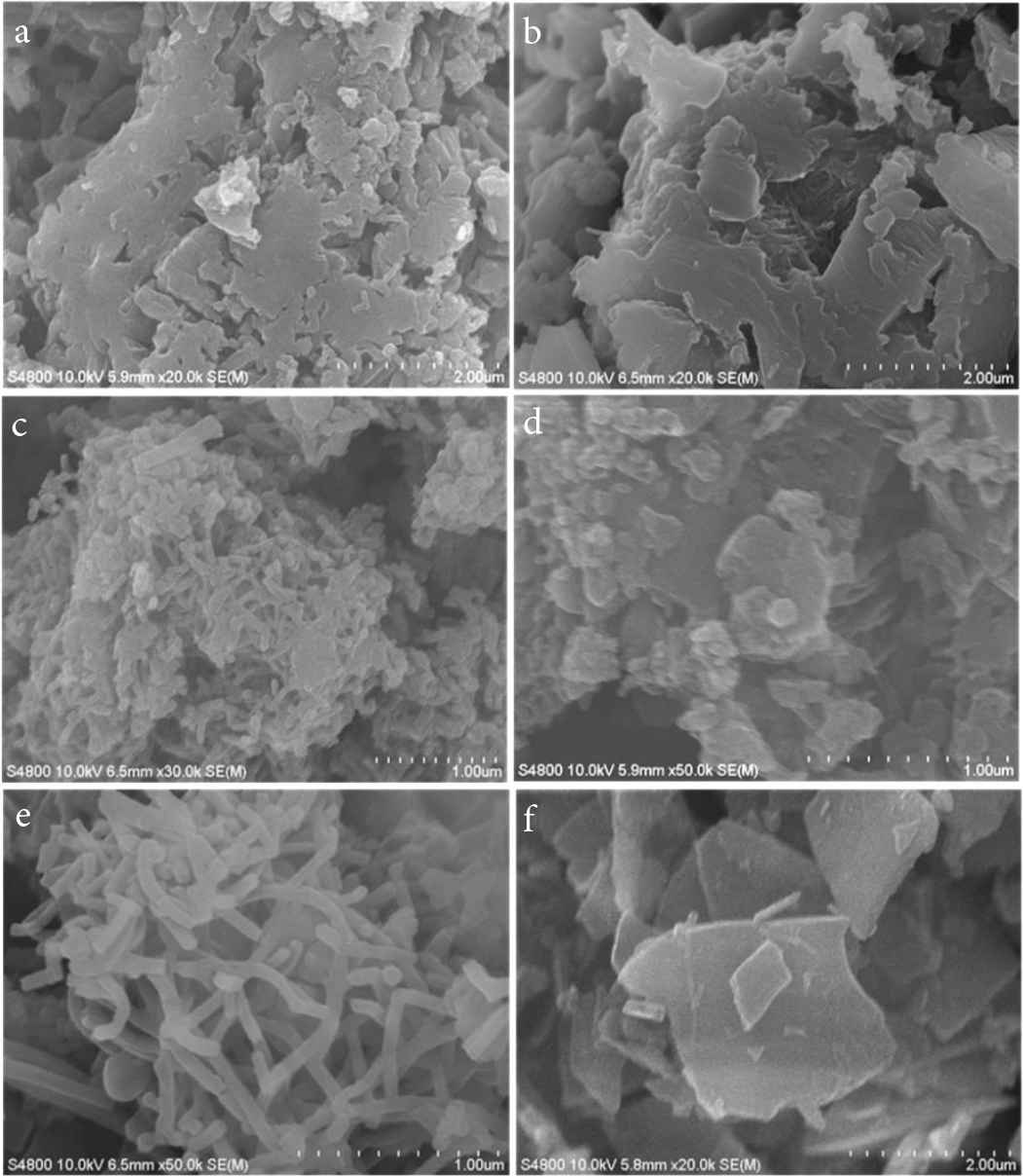
SEM images of PANI with mass ratio of aniline:citric acid: (a) 7:1, (b) 6:1, (c) 5:1, (d) 5:2, (e) 5:3 and (f) 5:4, corresponding to sample PANI 1–6, respectively.
Figure 3 presents the UV/Vis spectra of the doped PANI in water. The PANI-citric acid forms a black suspension (powders in Figure 1). Remarkably, these PANI-citric acid nanofibers have similar absorption peaks at 271 and 375 nm (Figure 3), citric acid is most likely tightly incorporated as anions within the PANI backbone during the in situ polymerization of aniline in citric acid solution. PANI 1 and 2 has absorbs peak 207 nm while PANI 3–6 absorbs 216 nm.
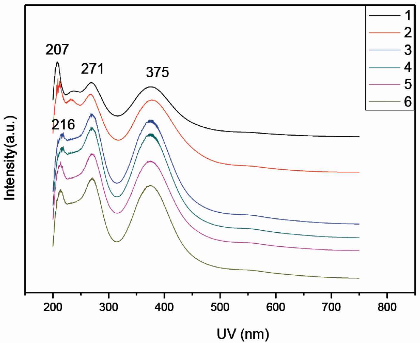
UV/Vis spectra of PANI 1–6 samples doped with citric acid, respectively.
Figure 4 shows a series of XRD patterns for confirming doping effects on PANI crystallization. It is worthy to mention that high crystalline structures have a similar strong peak at 2θ = 6.5°, 18.5° and 25.8°. It can be seen that PANI 1–6 have similar high crystallinity (about 70%). In proper doping level, PANI could crystallized and then self-assembled to form uniform shape and morphology such as 1D nanofibers by π–π stacking [17].
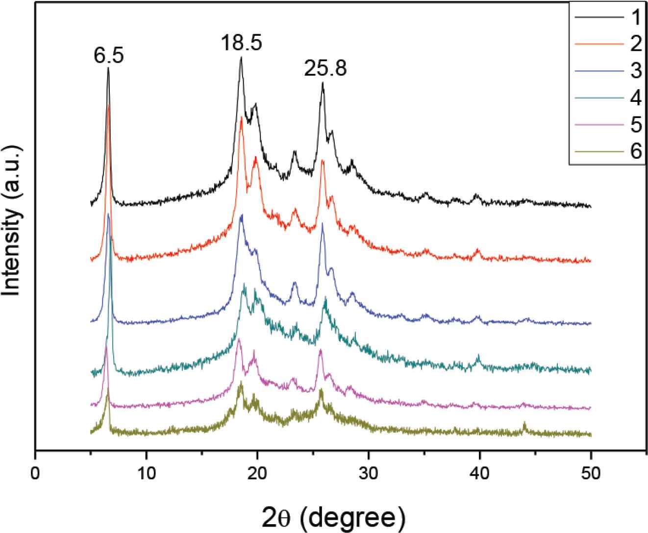
XRD patterns of PANI 1–6 samples doped with citric acid, respectively.
The measurement of conductivity is influenced by temperature, electrode constant and alternating current (AC) supply frequency. The measure of an object’s ability to conduct electricity is called conductivity G, which is the inverse of the resistance R. The electrochemical workstation tests the conductivity by connecting the four probes of the probe station with the four electrodes of the electrochemical workstation, and then selecting the cyclic voltammetry (CV) test method for testing. Conductivity of PANI-citric acid plates was checked by using a CINDBEST CS-6 four probe platform and a CHI660E electrochemical workstation, at room temperature. I–V curves identify typical semiconductor conductivity. Table 1 and Figure 5 show all PANI samples show an increased conductivity from 2.06 to 3.289 × 10⁻² S/cm along with mass ratio (aniline:citric acid) change form 7:1, 6:1, 5:1, 5:2, at last to 5:3. Moreover, the highest conductivity PANI-5 is one kind of nanofibers 3.289 × 10⁻² S/cm (red dot in Figure 6) rather than nanosheets PANI-6 with the ratio of 5:4. The reason is that nanofibers have 3D conductive networks while the nanosheets are not organized. Therefore, the PANI nanofibers with the highest conductivity are selected for raw materials of conductive ink.
| PANI samples | Aniline (g) | Mass ratio (aniline: citric acid) | APS (g) | Resistivity (102 Ω.cm) | Conductivity (10−2 S/cm) |
|---|---|---|---|---|---|
| PANI-1 | 5 | 7:1 | 5 | 0.485 | 2.061 |
| PANI-2 | 5 | 6:1 | 5 | 0.423 | 2.364 |
| PANI-3 | 5 | 5:1 | 5 | 0.386 | 2.591 |
| PANI-4 | 5 | 5:2 | 5 | 0.364 | 2.747 |
| PANI-5 | 5 | 5:3 | 5 | 0.304 | 3.289 |
| PANI-6 | 5 | 5:4 | 5 | 0.362 | 2.762 |
Conductivity test data of PANI-citric acid plates
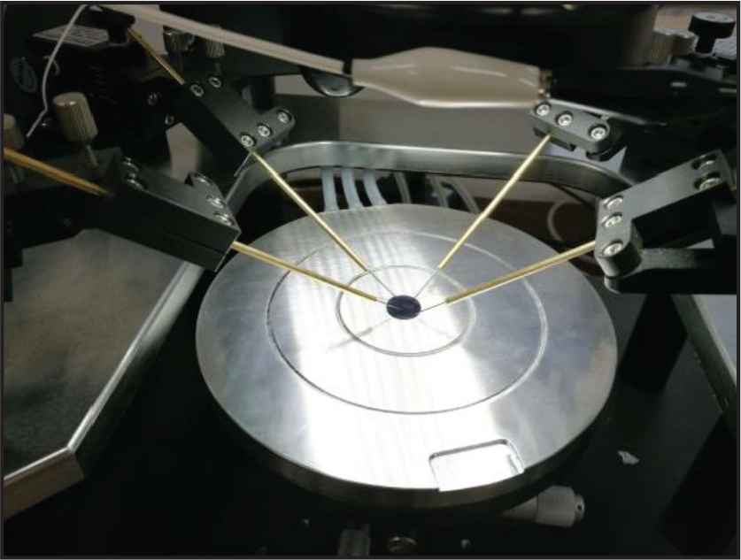
Conductivity test of PANI plates by the four probes platform.
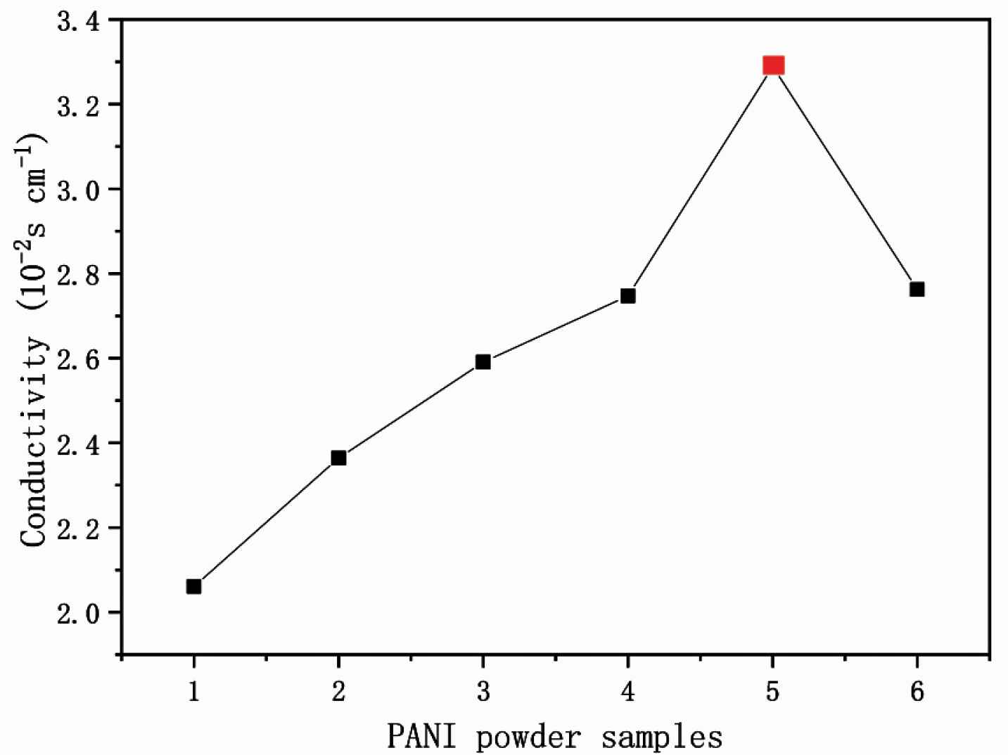
Conductivity of PANI 1–6. The red spot present in PANI-5, which has the highest conductivity of 3.289 × 10⁻² S/cm.
3.2. Polyaniline Inks: Ink 1–6
3.2.1. Characteristics of polyaniline ink
Figure 7 presents procedure of the preparation of PANI inks. Chinese word “一” (one) was written by using the PANI inks. The smooth surface of inks suggests uniform morphology and size of PANI nanofibers particles. Figure 8 presents PANI inks of Anhui University of Science and Technology university stamp. The inks generate an electronic circuit line where LED light can be turn on.

Procedure of the preparation of PANI inks. Chinese word “一” (one) was written by using the PANI inks.
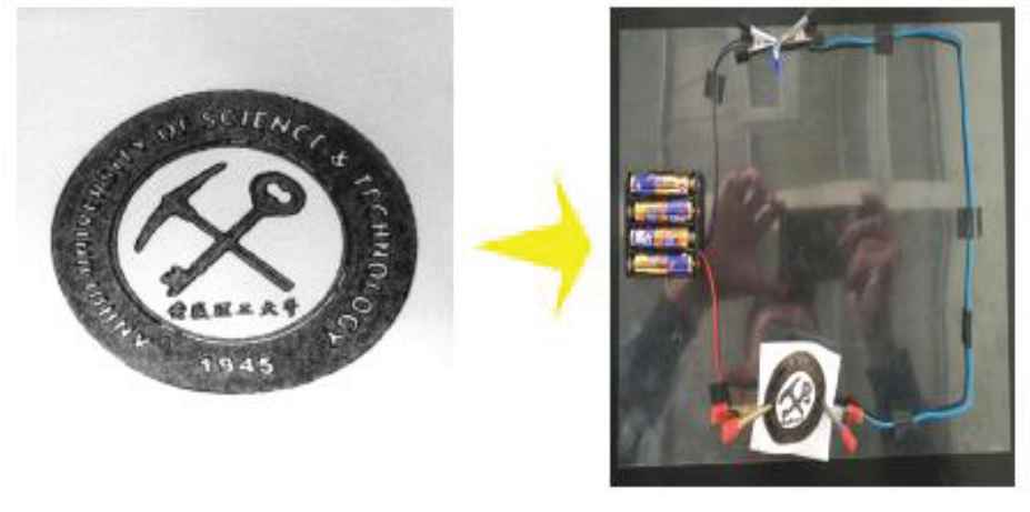
Photograph of circles with PANI inks stamp, which act as electronic circuit line.
SEM images show PANI inks in the surface of paper as seen in Figure 9. All PANI inks have the similar morphology with similar size of nanofibers because all PANI particles originate from PANI crystal nanofibers in PANI-5 sample.
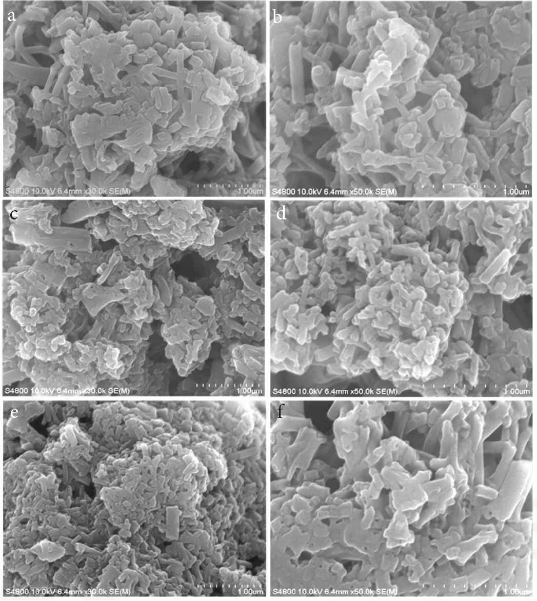
SEM images of (a–f) PANI inks in the surface of paper, corresponding to sample “Ink 1–6”, respectively.
The high crystallization rate of PANI nanofibers is beneficial to electron transport and the nanofiber structure of PANI has a higher specific surface area can be evenly dispersed in the ink matrix, which are conducive to the conductive properties of PANI. For deep understanding of the re-doping (PSS acid)/conductivity relationship, PSS content and conductivity of PANI crystal nanofibers doped with different content of PSS acid present in Figure 10, respectively. It can be seen that Ink-4 re-doped with relative high level of PSS acid (0.4 g) have higher conductivity (6.49 × 10⁻³ S/cm) than that in low level of <0.3 g PSS acid. If increase more PSS acid (0.6 g) in Ink-6, the conductivity decreases to 2.88 × 10⁻³ S/cm (Table 2). In fact, only proper doping level of PSS acid induces PANI to re-crystallization and self-assembly. The highest doping level of PSS acid (0.6 g) is harmful of conductivity. We can draw a conclusion that there is a strong correlation between conductivity and re-doping effect of PSS acid.
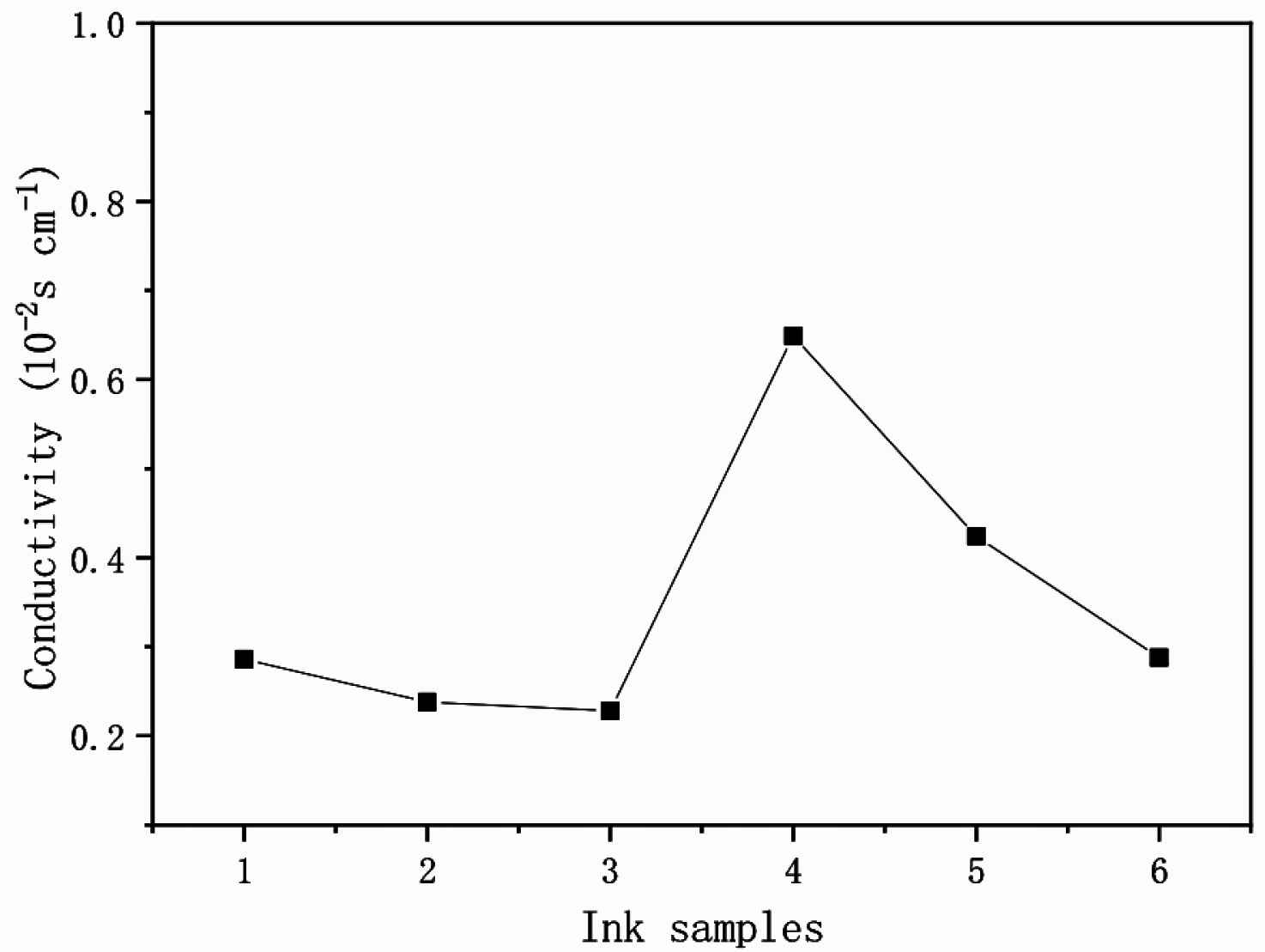
Conductivity of PANI Ink 1–6 samples.
| Ink samples | Aniline (g) | PSS (g) | PEG (g) | Deionized water (g) | Resistivity (102 Ω.cm) | Conductivity (10−3 S/cm) |
|---|---|---|---|---|---|---|
| Ink-1 | 1 | 0.1 | 0.2 | 2 | 3.50 | 2.86 |
| Ink-2 | 1 | 0.2 | 0.2 | 2 | 4.21 | 2.38 |
| Ink-3 | 1 | 0.3 | 0.2 | 2 | 4.38 | 2.28 |
| Ink-4 | 1 | 0.4 | 0.2 | 2 | 1.54 | 6.49 |
| Ink-5 | 1 | 0.5 | 0.2 | 2 | 2.36 | 4.24 |
| Ink-6 | 1 | 0.6 | 0.2 | 2 | 3.47 | 2.88 |
The conductivity data of PANI-citric acid inks
4. CONCLUSION
In conclusion, we demonstrate a new way to synthesize PANI nanofibers with high crystallinity (The crystallinity can be understood from the doped acid, because of the special structure of citric acid, which promotes crystallization.) and 3D conductive networks. PANI inks mixed with PEG and PSS were prepared and tested by using four probes under the microscope. PANI conductive ink is a kind of new conductive polymer inks, which could be used in electric devices with good electrical conductivity.
CONFLICTS OF INTEREST
The authors declare they have no conflicts of interest.
AUTHORS’ CONTRIBUTION
DL is responsible for the writing of the paper and the proposal of the experimental scheme. YL is responsible for the submission and the related matters. The other authors are responsible for the experimental optimization and data processing.
ACKNOWLEDGMENTS
The work is supported by National Natural Science Foundation of China (51775001), Anhui Primary Research and Development Program (1704e1002215), Natural Science Foundation of Anhui Province (1608085MB25), Postdoctoral Science Fund of Anhui Province (2016B108), Anhui Province Key Laboratory of Environment-friendly Polymer Materials, Anhui University.
REFERENCES
Cite This Article

TY  - JOUR
AU  - Dawei Li
AU  - Yulun Tao
AU  - Shun Yao
AU  - Wenxiang Tian
AU  - Guihui Wang
AU  - Baoyu Li
AU  - Wuji Wang
AU  - Shuo Li
AU  - Jinian Yang
AU  - Qingbo Yu
AU  - Shuxing Wu
AU  - Il Kim
PY  - 2021
DA  - 2021/03/26
TI  - Conductive Inks with 3D Conductive Networks of Polyaniline Crystals Nanofibers
JO  - Materials Highlights
SP  - 41
EP  - 45
VL  - 2
IS  - 3
SN  - 2666-4933
UR  - https://doi.org/10.2991/mathi.k.210322.001
DO  - https://doi.org/10.2991/mathi.k.210322.001
ID  - Li2021
ER  -


