 , I. Tavkhelidze2
Accepted 6 December 2020
Available Online 5 January 2021
- DOI
- https://doi.org/10.2991/gaf.k.201210.001
- Keywords
- Generalized Möbius-Listing bodies and surfaces
Möbius phenomenon
regular polygons
Gielis transformations - Abstract
In the study of cutting Generalized Möbius-Listing bodies with polygons as cross section, it is well known that the Möbius phenomenon, whereby the cutting process yields only one body, occurs only in even polygons with an even number of vertices and sides, and only in the specific when the knife cuts through the center of the polygon. This knife cuts from vertex to vertex, vertex to side or side to side, cutting exactly two points on the boundary of the polygon. This is called a chordal knife, in connection to the chord cutting a circle. If the knife is a radial knife, i.e. it cuts only one point of the boundary, the Möbius phenomenon can occur both in odd and even polygons, but only when the radial knife cuts the center of the polygon. One finding is the reduction of a problem in 3D (with internal geometry) to a planar problem and the concomitant reduction of the analytic representation with multiple parameters to a few only. The shape of the cross section and number of twisting in the 3D representation suffice and reduce the problem to cutting of regular polygons and cyclic permutations.
- Copyright
- © 2021 The Authors. Published by Atlantis Press B.V.
- Open Access
- This is an open access article distributed under the CC BY-NC 4.0 license (http://creativecommons.org/licenses/by-nc/4.0/).
1. INTRODUCTION
1.1. Generalized Möbius-Listing Bodies and Surfaces
Möbius bands are icons of mathematics, defined by a line swept along a circular path, but with a twist of 180° before connecting with the original line. Generalized Möbius-Listing
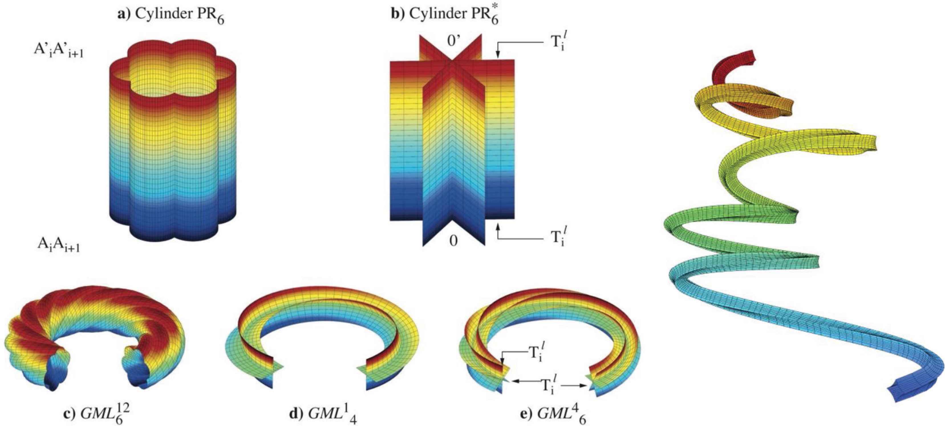
Left: Identification of vertices
Definition 1:
Generalized twisting and rotating bodies
The functions T1,2,3(t), R(ψ, θ, t), p(τ, ψ, θ, t), M(t) and Q(θ, t), as well as parameter μ (defining twisting around the basic line), define simple movements. With these analytic representations complex movements can be studied and decomposed into simple movements; this line of research goes back to Gaspar Monge [2].
Definition 2:
Generalized Möbius-Listing bodies
In the notation
The advantage of these analytic representation is the knowledge of the domain using a limited set of parameters to describe complex movements [2]. Furthermore, a wide variety of classical problems in topology, based on algorithmic approaches (e.g. folding and gluing) can now be studied using analytic geometry. Indeed, these analytic representations or equations substitute for recipes or algorithms to generate Möbius strips, tori, Klein bottles, canal surfaces or more complex shapes, or recipes for studying combinatorial problems, especially when these domains have internal symmetry whereby differentiated zones and sectors result when
1.2. Cutting of Möbius-Listing Bodies and the Reduction to a Planar Problem
In case the cylinder is a strip and it is given a half twist (180°) before joining, the classic Möbius band results, a
Definition 3:
Cutting is performed with (1) a straight knife, which (2) cuts perpendicular to the polygonal cross section of the
Depending on the number of twists, a number of independent bodies results, that is related to the divisors of m. Cutting of
Alternatively, one can also fix the knife and move the

(a) A pentagonal
Definition 4:
The analytic definition of d-knife (1) is a construction with straight lines, whereby the number of straight lines is either m or one of its divisors:
Indeed, with the analytical definition of the geometrical dm knife [11] all possible cuttings of regular polygons can be studied with the number of blades on the knife either m or a divisor of m. This dm knife with m blades cuts from vertex to vertex, vertex to side or side to side, with each blade cutting exactly two points on the boundary of the polygon.
In the case m = 8 the dm = m knife has 8 blades, but for the octagon one can also have one-bladed, two-bladed and four-bladed knives. In Figure 3 the results of cutting an octagon with the dm=8 knife with eight blades are shown. In the left figure one observes that dm cuts from vertex to the opposite vertex, but the analytical definition of the knife allows for a rotation resulting in the side to side cuts in Figure 3 (right). A translation or a combination of translation and rotation, resulting in vertex-to-vertex, vertex-to-side and side-to-side cuts is also possible (Figure 3, all other figures). This dm knife can cut from vertex to vertex, vertex to side or side to side, cutting exactly two points on the boundary of the polygon, and if m is an even number, then always some values of n exist for the Möbius phenomenon of the strip is realized.

Cutting and octagon with dm knife.
Remark 1:
It is noted that in the case m = 8 and the knife passing through the centre one counts only four chordal knives, but that is because the chordal knives overlap two by two.
The Annex in Gielis and Tavkhelidze [8] shows all possible cuts for m = 6,…,10. These methods are intimately linked to combinatorial problems, for example the Euler problems of drawing non-dissecting diagonals in polygons. Another combinatorial problem is the number of intersections of diagonals in the interior of regular n-gon. In the three left figures of Figure 3 the process of cutting from vertex to vertex is shown for an octagon. When these three figures are combined, one can compute the number of intersections of diagonals in the interior of regular n-gon (OEIS A006561 [13]). Indeed, Figure 3 is a dissection of this problem for the octagon into three, namely cuts with chordal dm knife from V1→V5 from V1→V4 and from V1→V3, using the analytic definition of knives (5), and rotation and translation of the knife. Diagonal cutting problems are vertex to vertex, but our methods can also handle VS and SS cuttings or drawing lines.
1.3. The Occurrence of the Möbius Phenomenon
It is noted that the solution of the problem by a reduction of dimensions, is also reflected in the reduction of parameters in the analytic expressions: only the cross section p(τ, ψ) and the twisting parameter n, are involved. With this reduction it was found that the Möbius phenomenon, whereby the cutting process yields only a single and “one-sided” body, similar to the original Möbius strip or ribbon, occurs only in even polygons with an even number of vertices and sides and only in the specific case when the knife cuts through the center of the polygon (Figure 3 left and right).
This means that after a full cutting of the
Remark 2:
In a classical Möbius band an arrow moving along the ribbon is reversed after one full rotation, and two rotations are necessary for the arrow to coincide with the original one. The phenomenon after one rotation is often referred to as non-orientability. In terms of visualization: if one travels on one particular trajectory of such one-sided ribbons resulting from cutting
For the necessary conditions for obtaining the Möbius phenomenon after cutting
- 1.
- 2.
The knife has m blades cutting all vertices with maximal length of the knife (i.e. from one vertex or side to the opposite one, then repeating this for every vertex).
- 3.
The dm knife has to cut through the center (cuts are either vertex to opposite vertex, or side to side through center of the polygon).
In investigating the conditions under which the Möbius phenomenon could also occur when m is an odd number (m = 3, 5, 7, …), we prove the following:
Proposition 1:
If the knife is a radial knife the Möbius phenomenon can occur both in odd and even polygons.
2. FROM CHORDAL TO RADIAL KNIVES
For a hexagon (Figure 4), one can visualize the m knives and their rotation for a d1 knife cutting from vertex 1 to 4 and for dm knife for all vertices. A translated knife is shown for d2. The rotated knives on the right show the orientation of the knife for every case when it cuts
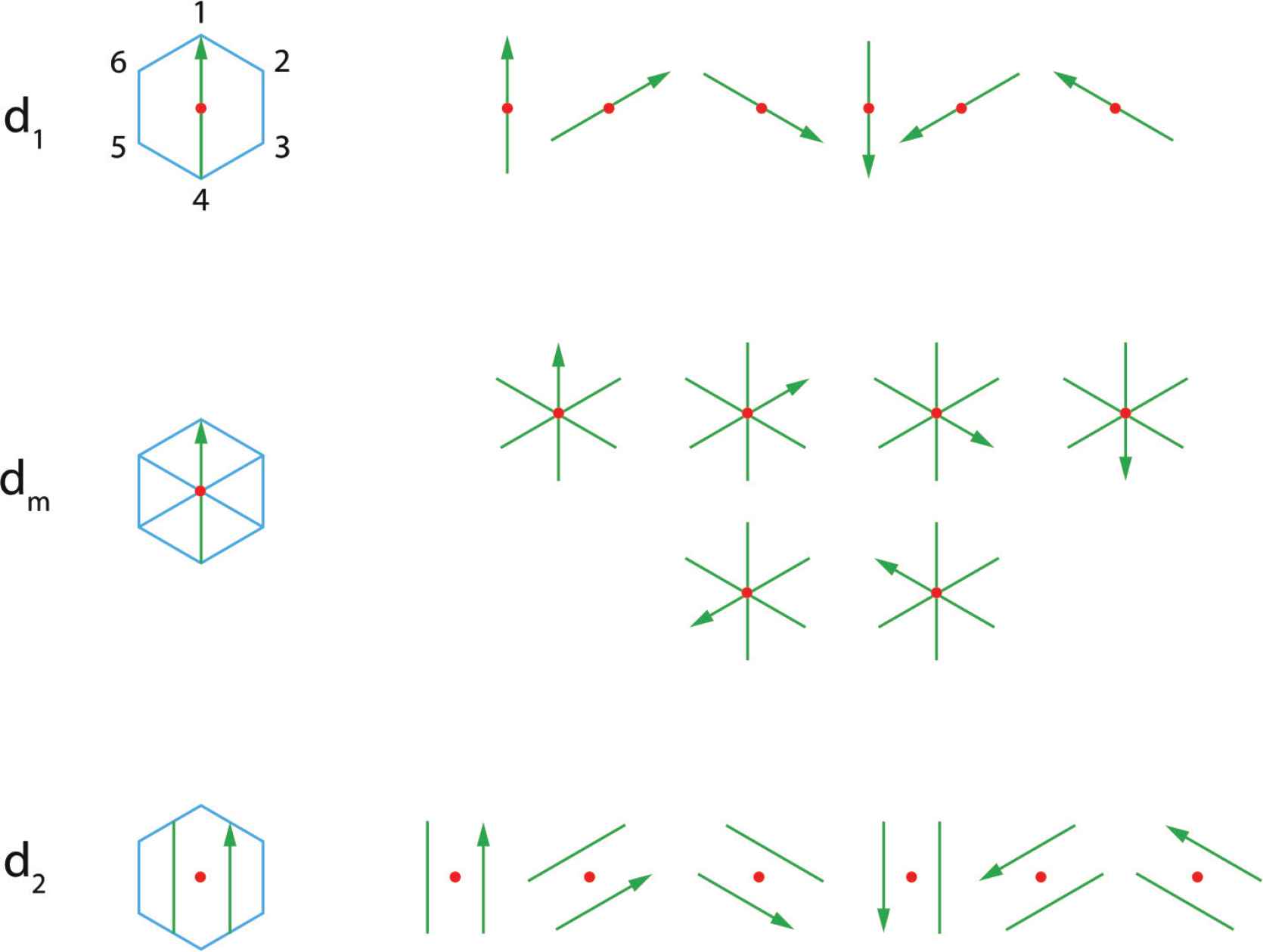
Chordal knife with 1, 2 and 6 blades.
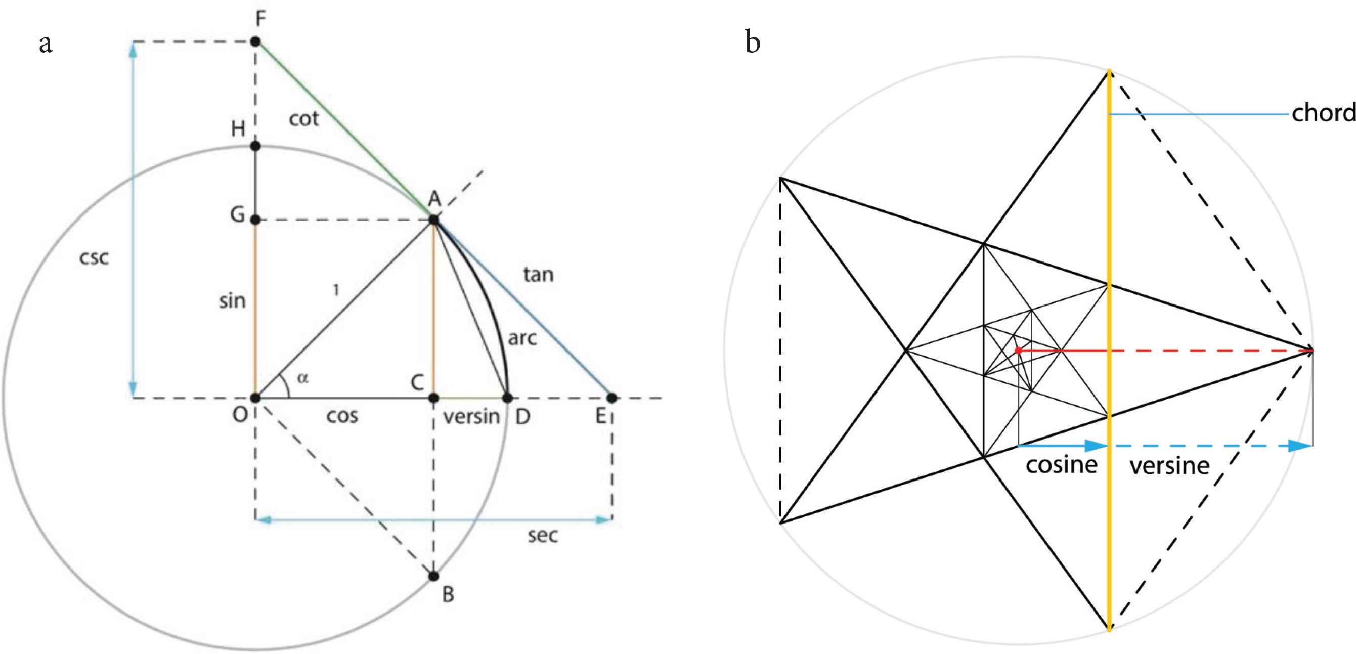
(a) Classical trigonometric functions with the radius OA as radial knife and the line AB as chordal knife. (b) Rotating and zooming the yellow knife allows for the infinite scaling of the pentagon and pentagram.
In Figure 5a the line OF corresponds to half the knife d1 in Figure 4. For this chordal knife in vertical direction and going through the center the chord is maximal; the sine equals 1 and the cosine equals zero. The line AB on the other hand corresponds to the translated knife in the case of knife d2 in Figure 4.
In Figure 5b the relation of chords to polygons is shown, with the chord, the cosine/versine and sine/coversine as interesting functions for the pentagon. On a circle five equally spaced points represent the vertices of a pentagon, which is constructed by connecting vertex Vi with vertex Vi+1, then vertex Vi+1 with Vi+2, until one returns at vertex Vi. The pentagram is constructed by connecting vertex Vi with vertex Vi+2 (Figure 5b).
In particular the adjacent chords of the pentagram (e.g. the yellow chord from V1 to V3 and the chord from V3 to V5) form two long and equal sides of a so-called golden triangle, an isosceles triangle with one angle
If we now limit the knife in (5) to the half line OF or OE originating in the origin or center of the polygon, we obtain a radial knife (Figure 6). The name derives from radius versus the diameter in chordal knives. It cuts the polygon boundary only in one point.

Left: drc radial knife originating at the center (d1). The other rotated arrows indicated the position of the radial knife when traveling around a
Remark 3:
Chordal and radial knives can belong to four different classes:
Remark 4:
A radial cut drc is also a half-line or ray, corresponding to the classical position vector, the most elementary and natural geometric object. This half-line can be translated using δ or rotated using α, the translation and rotation parameters in (5), respectively. The drc or
The dm = dcc knives found their origin in cutting of bamboo culms lengthwise. Examples of both chordal and radial knives are found in the art of wood sawing, where due to the nature of wood, saws are more efficient than knives (Figure 7). Plain sawing corresponds to using chordal saws, whereas for quarter and rift sawing, the saw is a radial saw, with drc in the case of rift sawing and
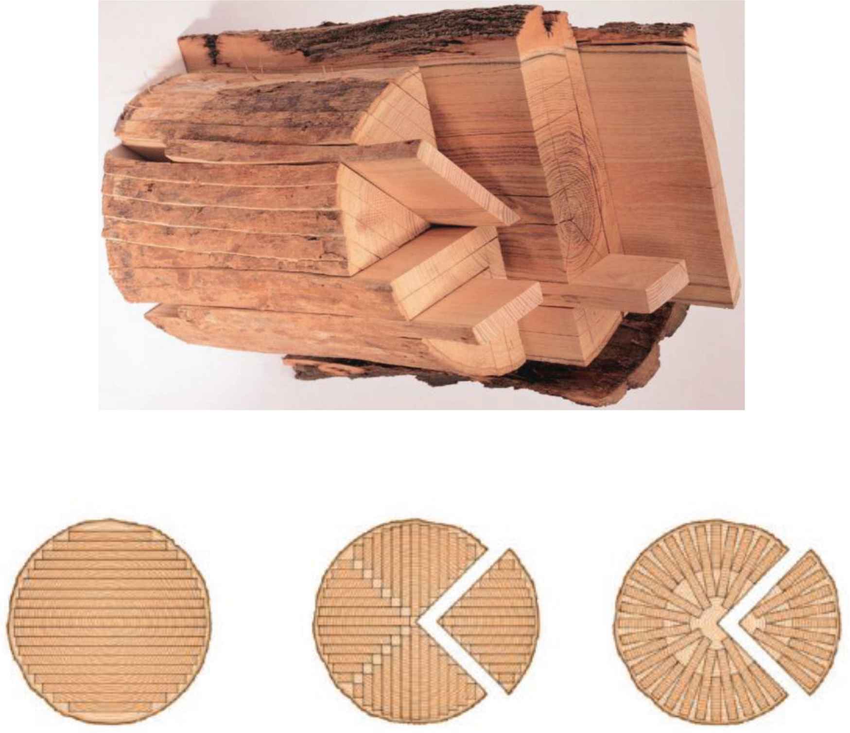
Plain, quarter and rift sawing of logs.
3. USING RADIAL KNIVES FOR ODD AND EVEN POLYGONS
3.1. The Conditions for Odd
Now, for proving that the radial knife also works when m is an odd number, the strategy is to look only at the simplest possibility, which for m even is a cut through center or origin from a vertex to the opposite vertex, for all vertices (Figure 4 left and dm in Figure 4). In this case the planar geometrical configuration is m/2. In 3D
Because of the equivalence of the cutting of
It is then required to have the same situation in odd polygons. It is easy to see that this is very well possible with radial knives as shown in Figure 6, but five radial knives are needed orin general, an amount of m knives, in contrast to an amount of m/2 of chordal knives as in dm in Figure 6. Generalizing radial knives drc for any symmetry, i.e. rotating the radial d1 knife to m positions as in Figure 8, results in m radial knives for m-regular polygons, irrespective of whether m is even or odd. In 3D

Five radial knives in a pentagon.
3.2. Zones Created with Cutting
Using chordal knives in polygons results in different zones, the number and shapes of which are defined by the mode of cutting [12]. In Figure 3, some examples are shown for octagons. The different colors of the zones correspond to different bodies resulting from cutting
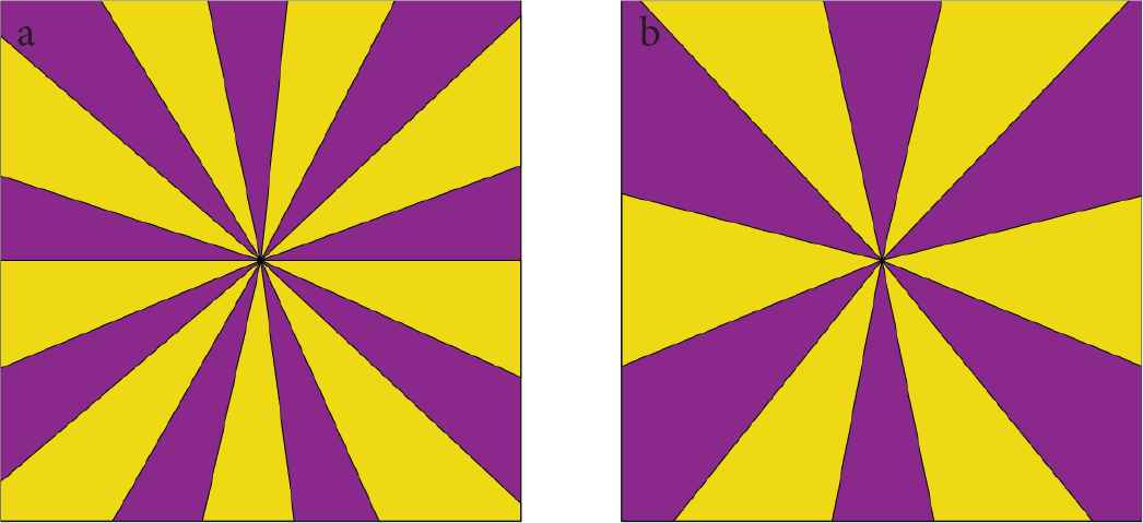
Number of zones created with chordal knife with m blades through the origin and vertices for m = 9 (a) and m = 12 (b).
In the case of radial knives however, the number of sectors is m, irrespective whether m is even or odd. In Figure 10 this is shown for cutting of equiangular triangles, with chordal knives through the origin from vertex to side (Figure 10a) or from side to side (Figure 10c). The number of different chordal knives m = 3 results in 2m = 6 sectors. If the cut is performed with three radial knives starting from the origin to vertex or two sides, one obtains exactly m sectors, for both odd and even polygons (Figure 10b and 10d). These sectors are a combination of one light blue and one dark blue sector in Figure 10.

Vertex to side and side to side cuts through the origin in a triangle, with chordal (a and c) or radial knives (b and d).
This leads to three sectors which are congruent. Likewise, when the knives are rotated, always three congruent sectors are obtained. In the 3D
Congruence of sectors in the planar view is of primordial importance. These congruent sectors are independent of the number of cuts with the radial knife, but only in the case that the number of knives used is m, the Möbius phenomenon occurs. In other words, only in that case one body results after cutting the GML body. The cross section of this single body is the same along the whole GML body, due to the congruence of shapes.
With the demonstration in 3D in Subsection 3.1 and the congruence of sectors in planar view, we then have [14]:
Theorem 1:
If the knife cutting a
4. RADIAL KNIVES AND LAMÉ’S SUPERCIRCLES
One constant result in the studies of cutting
A main strategy in our joint studies are the analytic representations. These are threefold: namely (1) the analytic representations of
First, classic Möbius ribbons or strips where generalized to
Second, the extension with Gielis transformations both for cross sections and the basic line of the toroidal structure, showed the generality of the results. They act as a transformation on curves or functions f(ϑ) and are a generalization of Gabriel Lamé’s superellipses, defined by
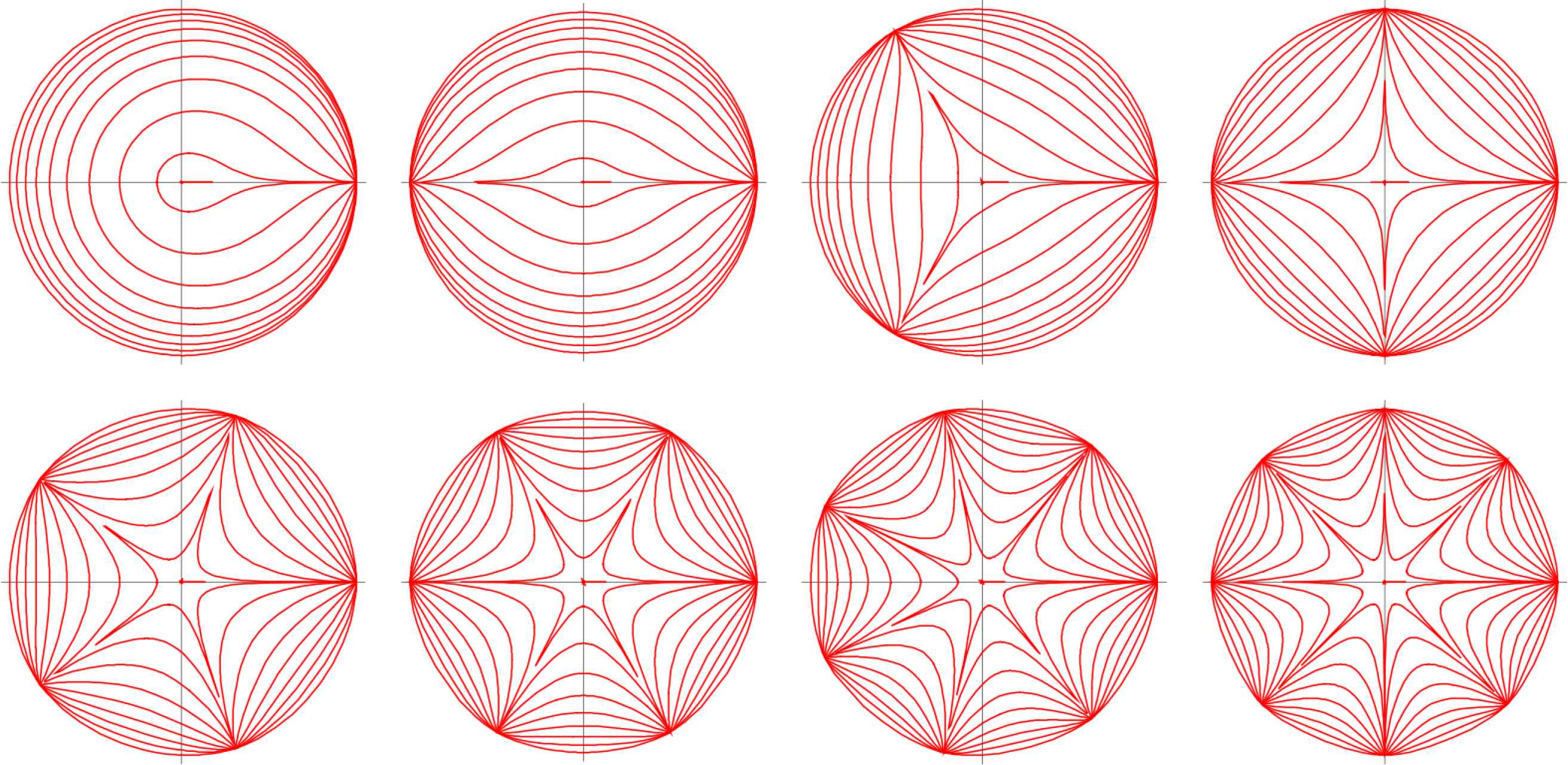
Supercurves with all exponents n equal, but m = 1, 2, …, 8. All exponents n1 = n2 = n3 ≤ 2. Subcircles for m = 4, upper right.
Expression (4) is a Pythagoras-compact expression, since for n1, n2, n3 = 2; A = B = 1; m = 4. in (4), the circle results. Parameter m can be an integer, a rational or irrational number, and (4) can define the cross section or the path, or both. By considering (4) as inequality, any point inside (and/or outside) the curve is defined precisely. Obviously, one can define shapes with boundary thickness (annuli or shells) in this way.
Remark 4:
Any of the curves in Figure 12 may serve as boundaries or as knives [8]. Similary, straight lines in the Poincaré disk, the two-dimensional representation of the hyperbolic plane, can serve as knives.
Third, the results of cutting of
The results in this paper is that the same analytic representation of a dm knife but restricted to a half line resulting in radial knives, can be used to extend the possibility of having a single body with Möbius phenomenon after cutting GML bodies, with cross section regular polygons with both even and odd rotational symmetry. In this case, bodies (or polygons) are cut, but beyond cutting radial knives can also divide the plane into m sectors (chordal or diagonal knives divide the plane into m/2 sectors). By adding a direction and a length to these radial knives, this results in vectors. In other words, the same analytical definition adapted for radial knives, can describe knives, lines to separate sectors, drawing tools (e.g. drawing diagonals in polygons) or vectors. If we would call the radial knife an rm knife, it is clear that it is directly related to radial distances, but now with m copies of one knife, spaced equally around the origin.

The rope model of the helical heart.
Finally, a beautiful consequence is that if one applies Lamé’s idea of generalizing circles and ellipses into supercircles and superellipses defined in a Cartesian system with four quadrants, onto a plane divided into m sectors, one readily sees that the Gielis formula (4) is exactly doing the same as the knives: division of the plane into m sectors. To each of these sectors then Lamé’s generalization of the Pythagorean Theorem can be applied. At the same time (4) adds more degrees of freedom and it is a continuous transformation. So we find a complete integration of Gielis Transformations and
5. CONCLUSION AND FUTURE WORK
5.1. Biology, Physics and Geometry
The combination of chordal and radial knives and their analytic representation is directly related to classical trigonometric functions and the position vector. Because of the combination with Gielis transformations, it is expected that many of the phenomena described above, will find use in many fields of physics and biology [8].
One particular example of a shape that can directly be interpreted as a
It is remarkable that the connection of geometry to the real world can come in many ways. Classic processes in the bamboo and wood industries inspired the solution with chordal and radial knives in cutting
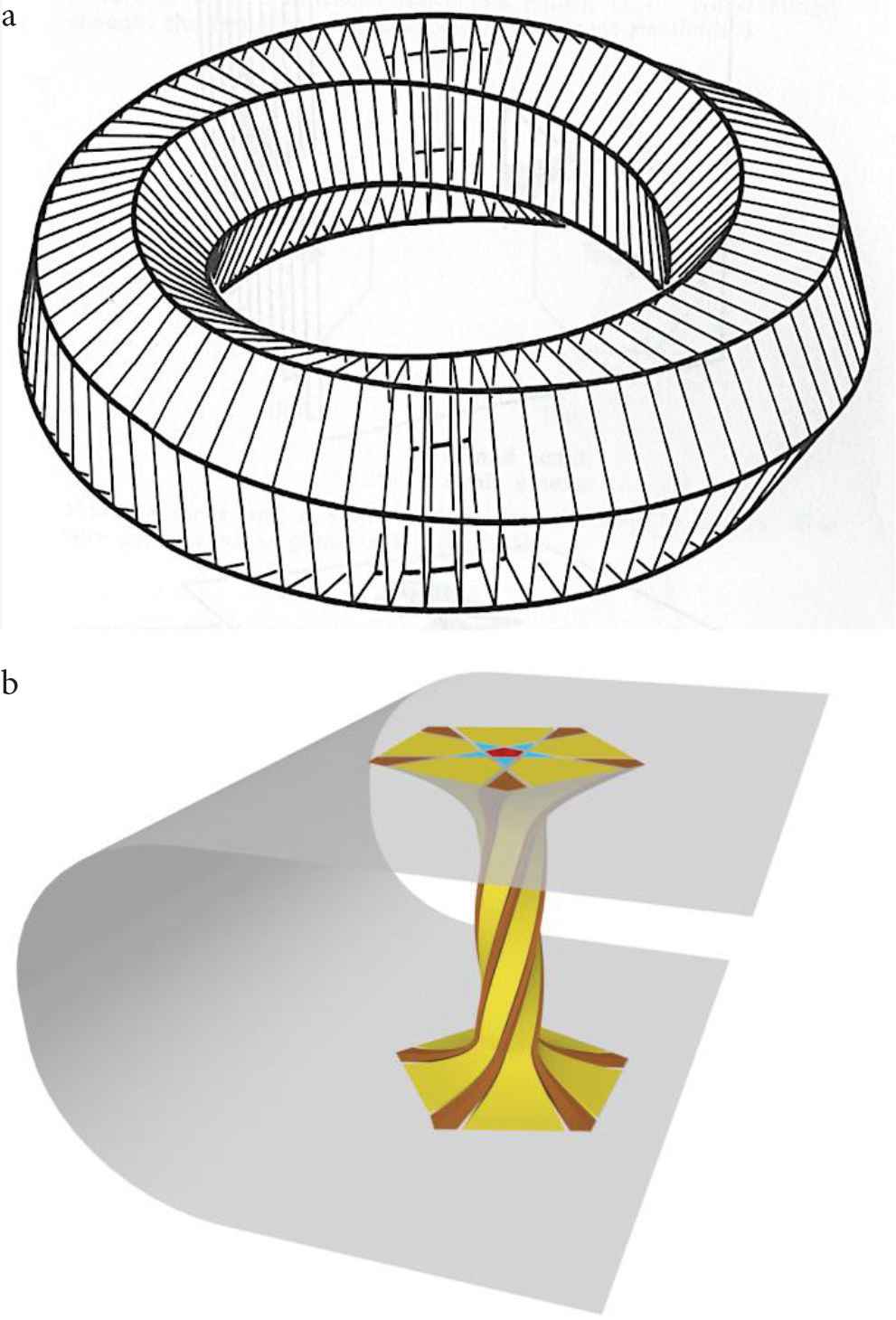
Figure 13a shows a fibre bundle, and just as the Möbius band is a nontrival example of a fibre bundle,
(a)
5.2. Gielis Transformations
The analytical representation of chordal and radial knives is directly related to classical trigonometric functions and the position vector. In this respect, Gielis transformations provide for a stretchable position vector [10]. In its original formulation it describes simple curves from [0, 2π] for integer m and from [0, k2π] for m = p/q with p and q relative prime, but different sectors of a curve or disk with different parameters can be defined with the appropriate transition functions, resulting in variational supercurves (Figure 14). Further generalizations, retaining the Pythagorean compact structure, include the use of different functions instead of trigonometric functions in the denominator of Equation (4) [20].
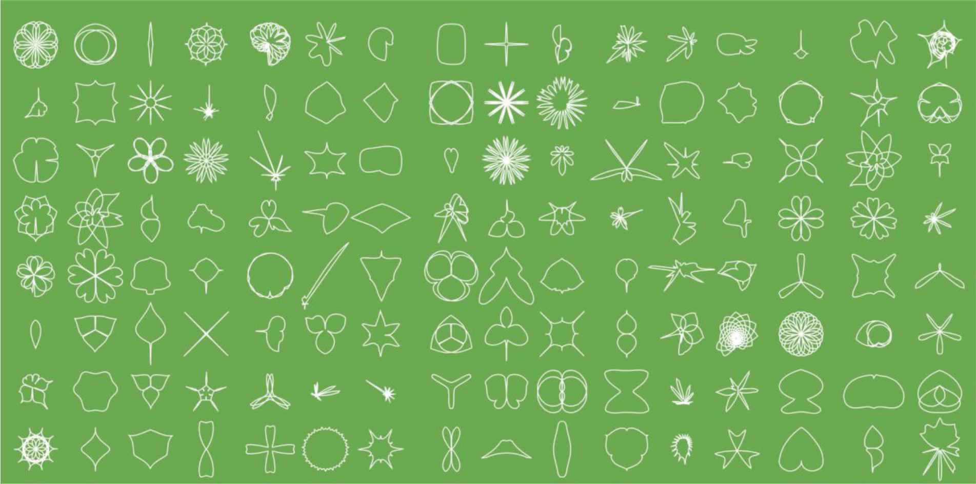
One can also make any number of shapes with the following analytical representation [21].
The unified geometrical description of GML surfaces and bodies and Gielis’ transformations allows for the exact description of irregular shapes using an analytical formula and this translate into the possibility of building flexible tools to carry out sensitive analyses to geometrical parameter variations.
CONFLICTS OF INTEREST
The authors declare they have no conflicts of interest.
SUPPLEMENTARY MATERIALS
- •
Tables cutting GML4 and GML5.
- •
Videos of chordal and radial knives.
Supplementary data related to this article can be found at
REFERENCES
Cite This Article

TY  - JOUR
AU  - J. Gielis
AU  - I. Tavkhelidze
PY  - 2021
DA  - 2021/01/05
TI  - The Möbius Phenomenon in Generalized Möbius-Listing Bodies with Cross Sections of Odd and Even Polygons
JO  - Growth and Form
SP  - 1
EP  - 10
VL  - 2
IS  - 1
SN  - 2589-8426
UR  - https://doi.org/10.2991/gaf.k.201210.001
DO  - https://doi.org/10.2991/gaf.k.201210.001
ID  - Gielis2021
ER  -


